Isa tarafından yazılmıştır
Hi. Last time we mentioned the basics and set up a PC-PC network. Now we will go into more detail about Packet Tracer.
Naturally, not every network devices connect with the same cable type as there are lots of them. Some connect with fiber cable, some with another. So, we should choose the right cable for a successful connection.
Cable types can be seen in Packet Tracer.

connections
We will move on referencing this cheat sheet of cable types:
Cross-over cable
Straight Cable

copper cross-over
Drag two computers and choose Cross-Over cable. Then, right-click on PC0, click FastEthernet0.
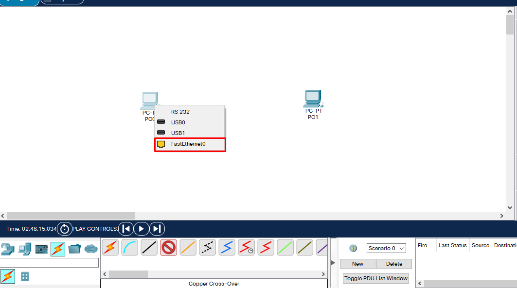
Cross-over-1
Now we have another tip to connect another device. Click PC1, choose FastEthernet0 for that.
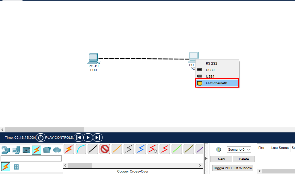
Cross-over-2
We have a successful connection. You can tell that from the green arrows appearing on the cable.
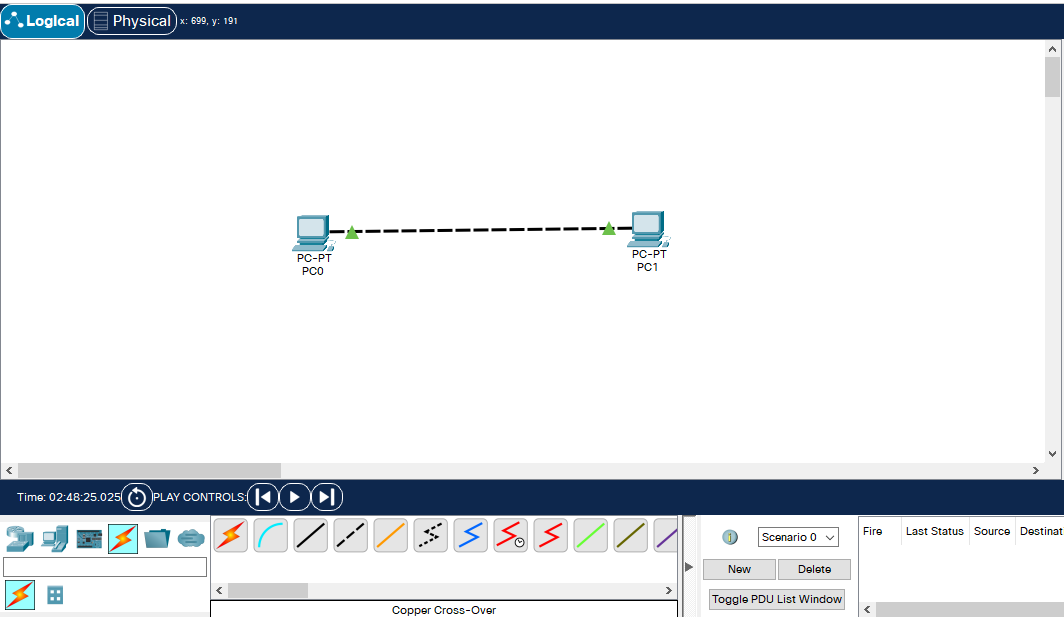
Cross-over-3
You can do this with other devices too. Let’s do another one on Hubs
Drag two Hubs from NetworkDevices and connect them with Cross-over.
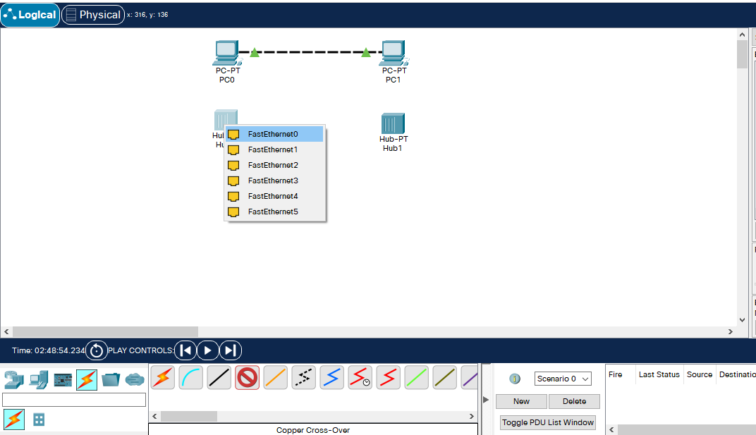
Cross-over-4
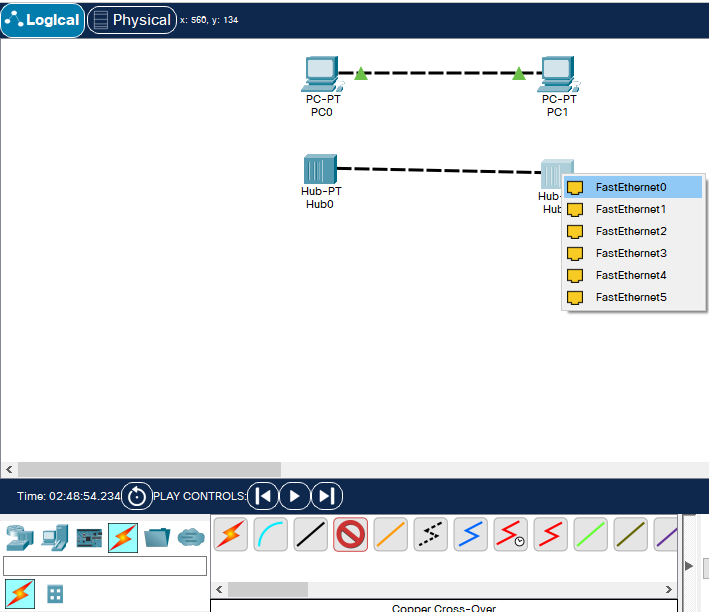
Cross-over-5
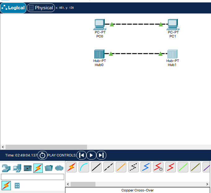
Cross-over-6
PC and Hubs work fine plugging and unplugging if there are no logical mistakes.
But with Switches, it works differently. Because they don’t light green after plugging.
Choose GigabitEthernet0/1 on Switches with Cross-over cables.
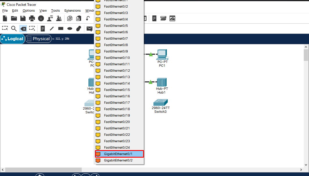
Cross-over-7
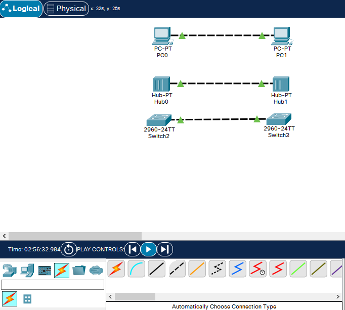
As you can see, Switches don’t directly go green like others. It’ll go green in a minute.
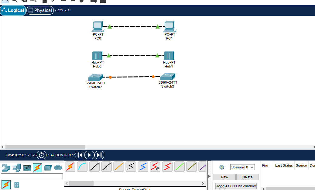
Cross-over-8
Why this happens is because the interfaces in Switch do STP protocol and it takes about a minute to do that, then it’s green.
Cross-over-9
If it doesn’t go green in a minute, speed up the time from Play Control below.
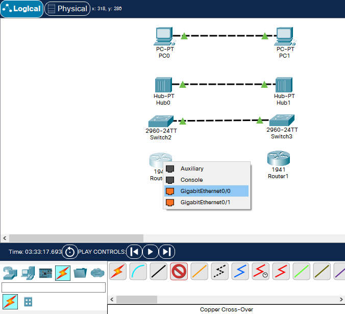
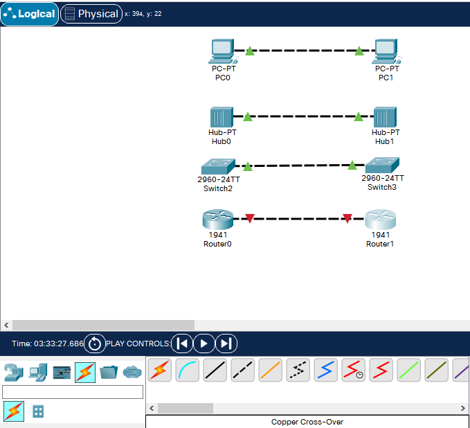
With PC-PC, Hub-Hub, and Switch-Switch networks, a configuration isn’t needed, unlike Routers. Routers won’t connect without a configuration.
Cross-over-10
Cross-over-11
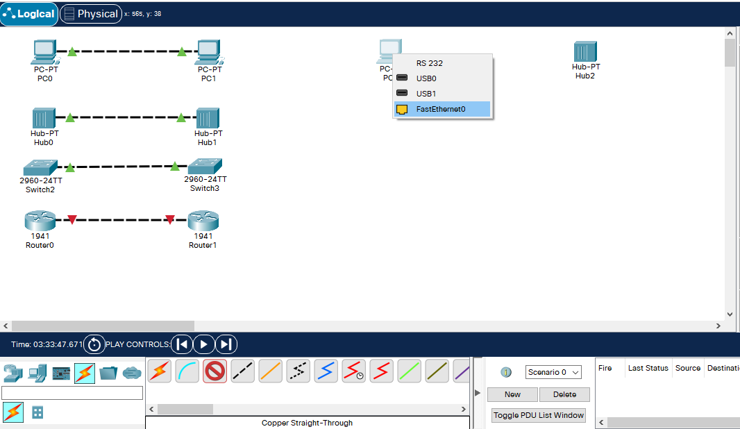
You need a straight-through cable for, say, PC-Hub. Choose FastEthernet0 with both having straight-through cable.
Straight-Through-1
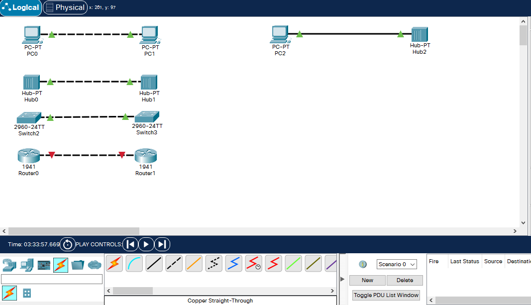
Straight-Through-2
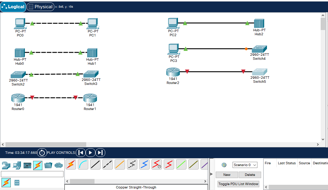
Straight-Through-3
Switch-Router and Router-Hub connections will always light red unless you configure the Router.
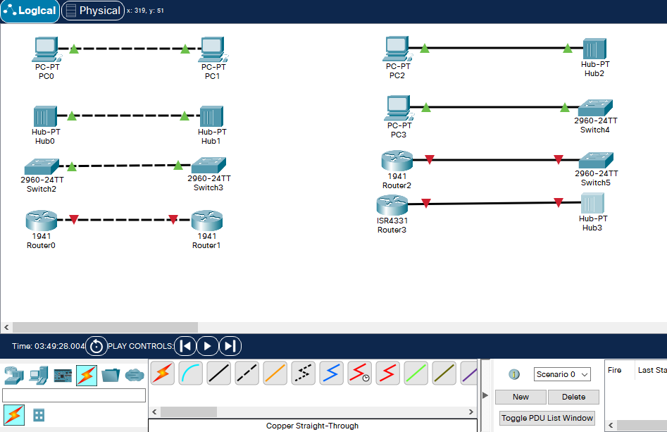
Straight-Through-4
Here as you can see, the same devices have Cross-over, and different devices have StraightThrough cables. Except for the PC-Router connection which has the Cross one.
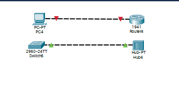
Cross-over-13
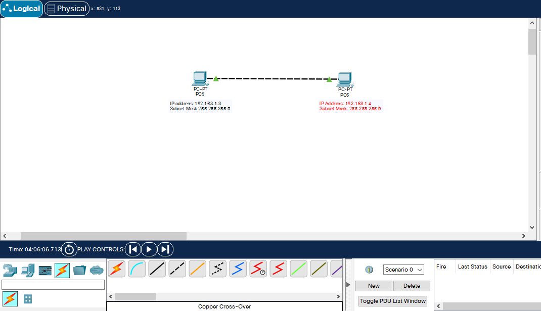
With the Packet Tracer’s feature, I mark the IP addresses for devices. You could use the N shortcut for that.
IP atama-1
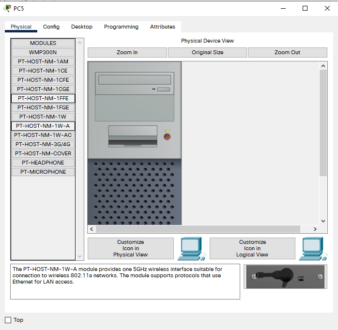
To assign, click one of the devices. You should see something like this:
IP atama-2
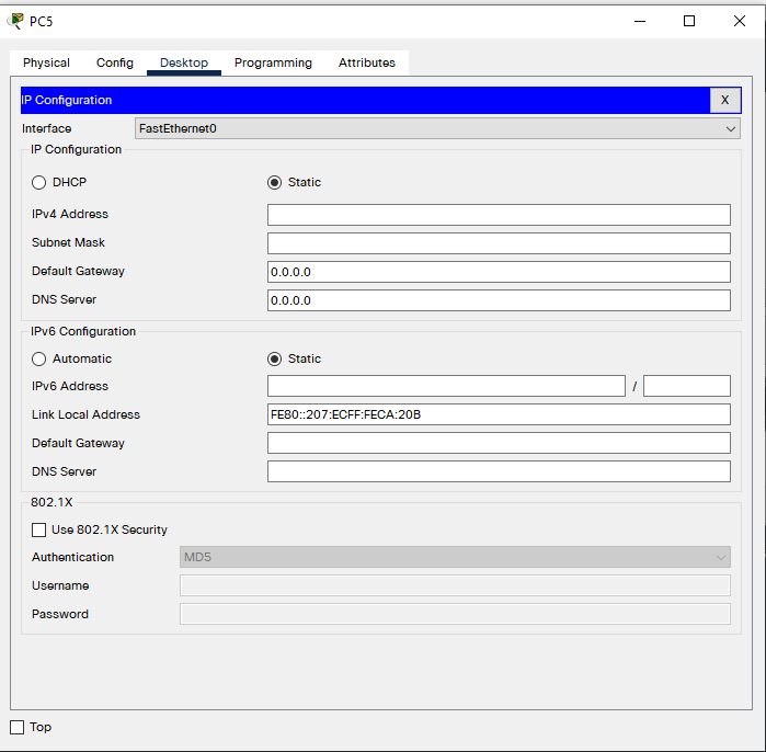
Click Desktop, then IP Configuration.
IP atama-3
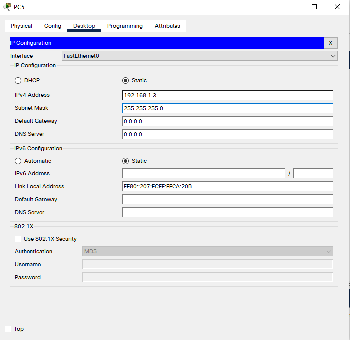
Assigning can be done in both ways: with DHCP or manually. To assign manually, type the IP address somewhere about IPv4 Address. It defined Subnet Mask itself.
IP atama-4
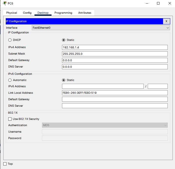
Do the same with the other device:
IP atama-5
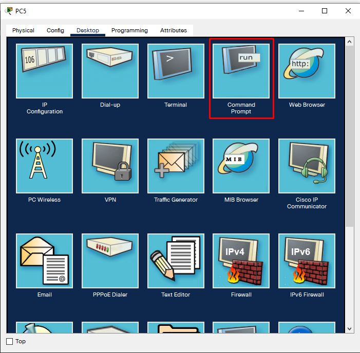
Now the addresses are defined but we don’t know if there is anything incorrect. To test for it, use Command Prompt. To do so, click the device once more, then choose Command Prompt from Desktop.
IP atama-6
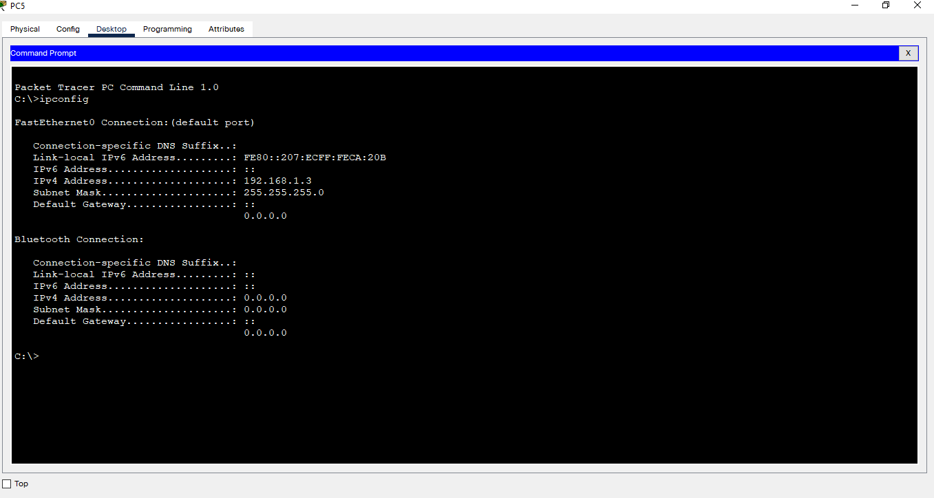
Do ipconfig to see the IP address:
Font Size – 3
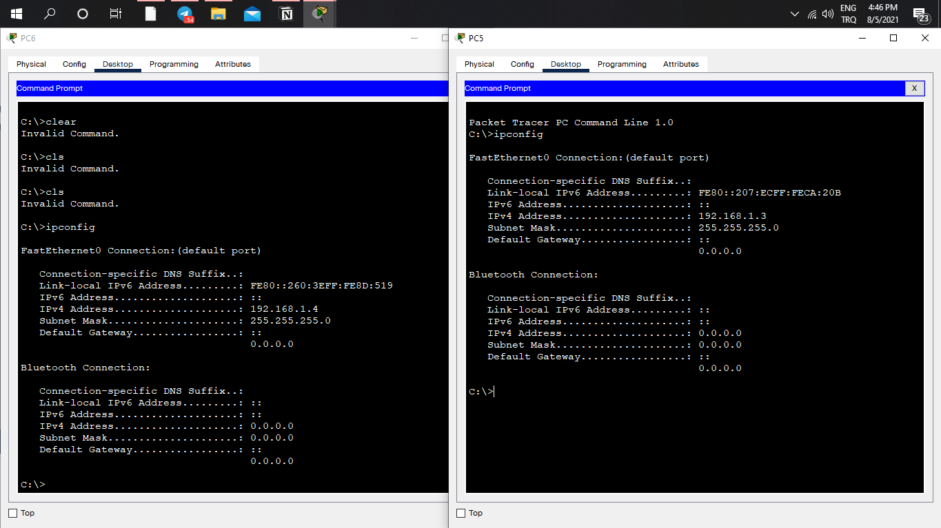
IP addresses are correctly assigned as we defined.
IP atama-8
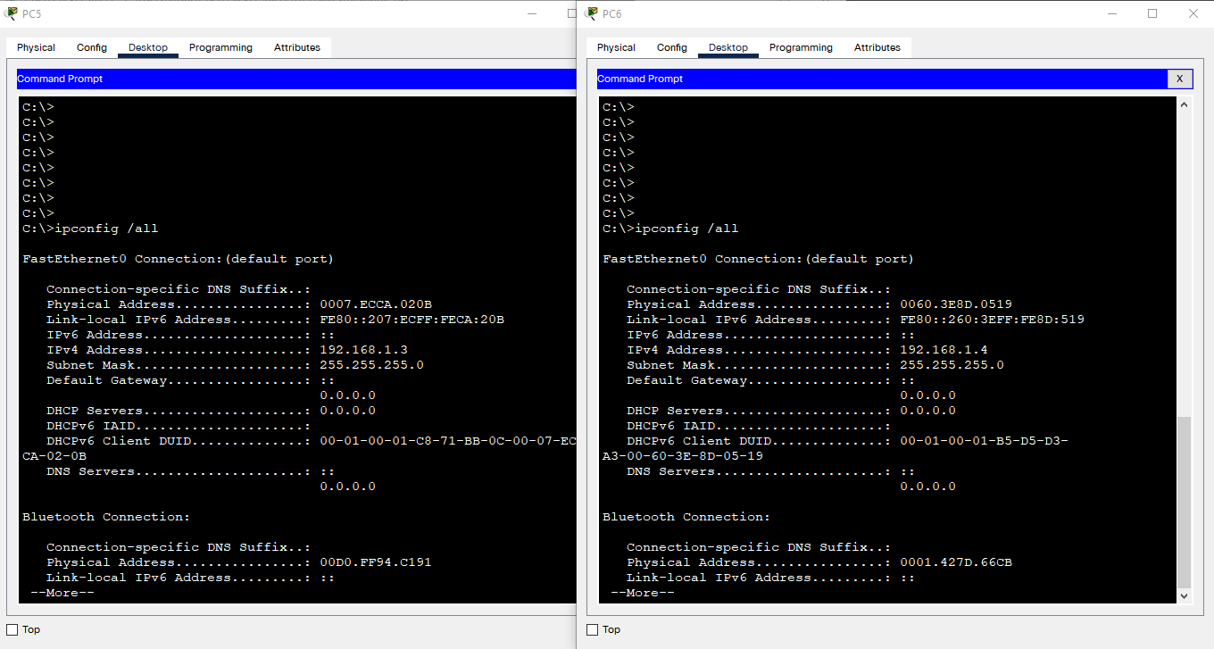
To channel in-network, Devices require MAC addresses too.
MAC Address Configuration.
MAC Adresses are structures made up of 48 bits.
Do ipconfig /all to view a MAC address.
MAC-Address-1
That’s all to know about MAC Addresses for now.
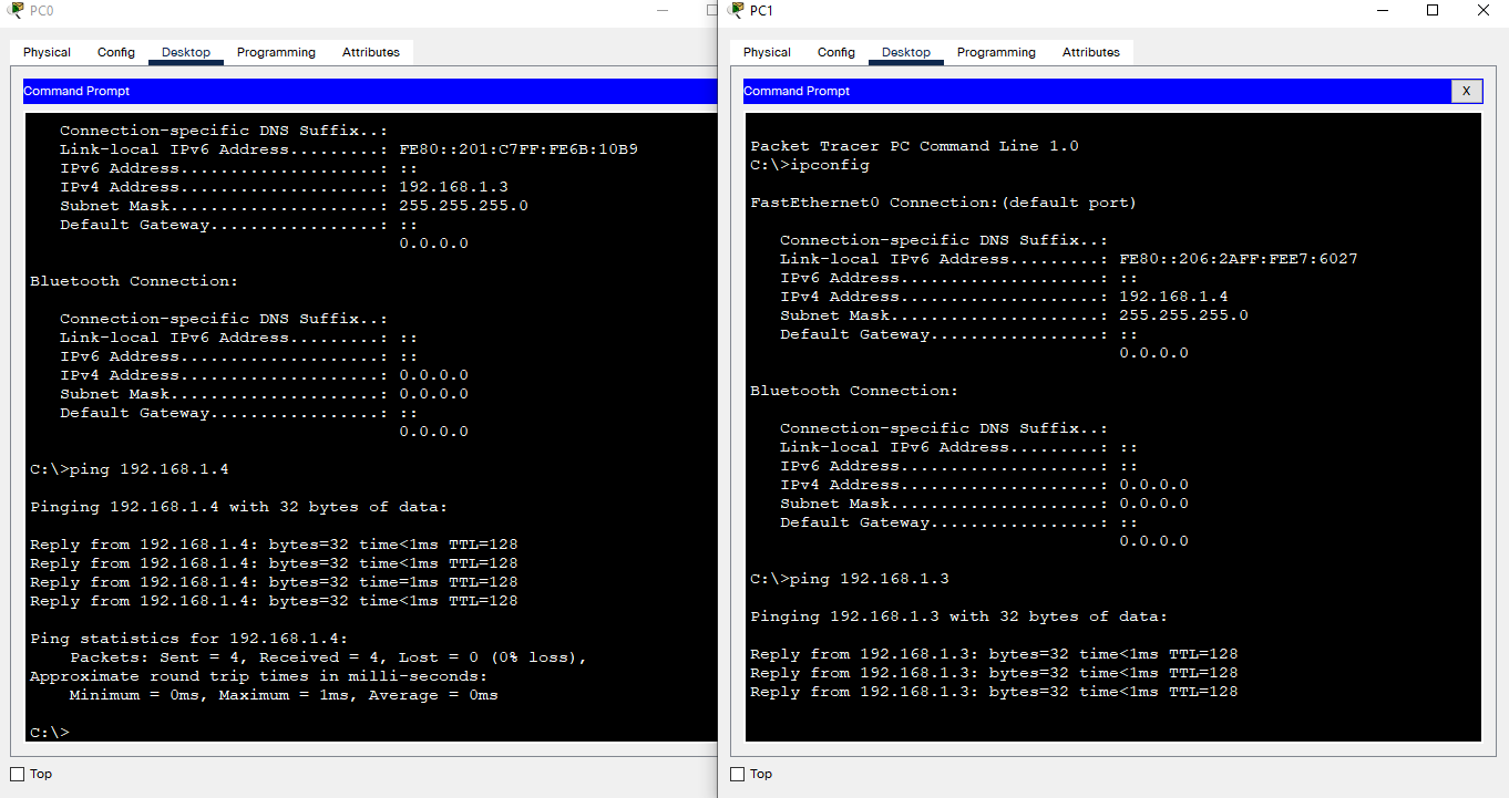
Now we will have to check if the devices can channel each other. For that, do ping [other device’s IP address]
ping-1
If you can ping a device, you are able to channel that device.
Ping uses a protocol named ICMP. ICMP is used to see network devices’ state. The image shows that 32-byte packets arrive below 1ms. Sending 4 packages, 4 packages arrived. 8 Packages are mutually being sent or received.
ping-2
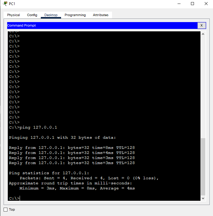
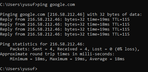
You don’t just check on local devices with ping. You can also check with Public servers. Try this on your own device. Packet Traces can’t connect to our home networks.
Open CMD, do ping google.com
ping-3
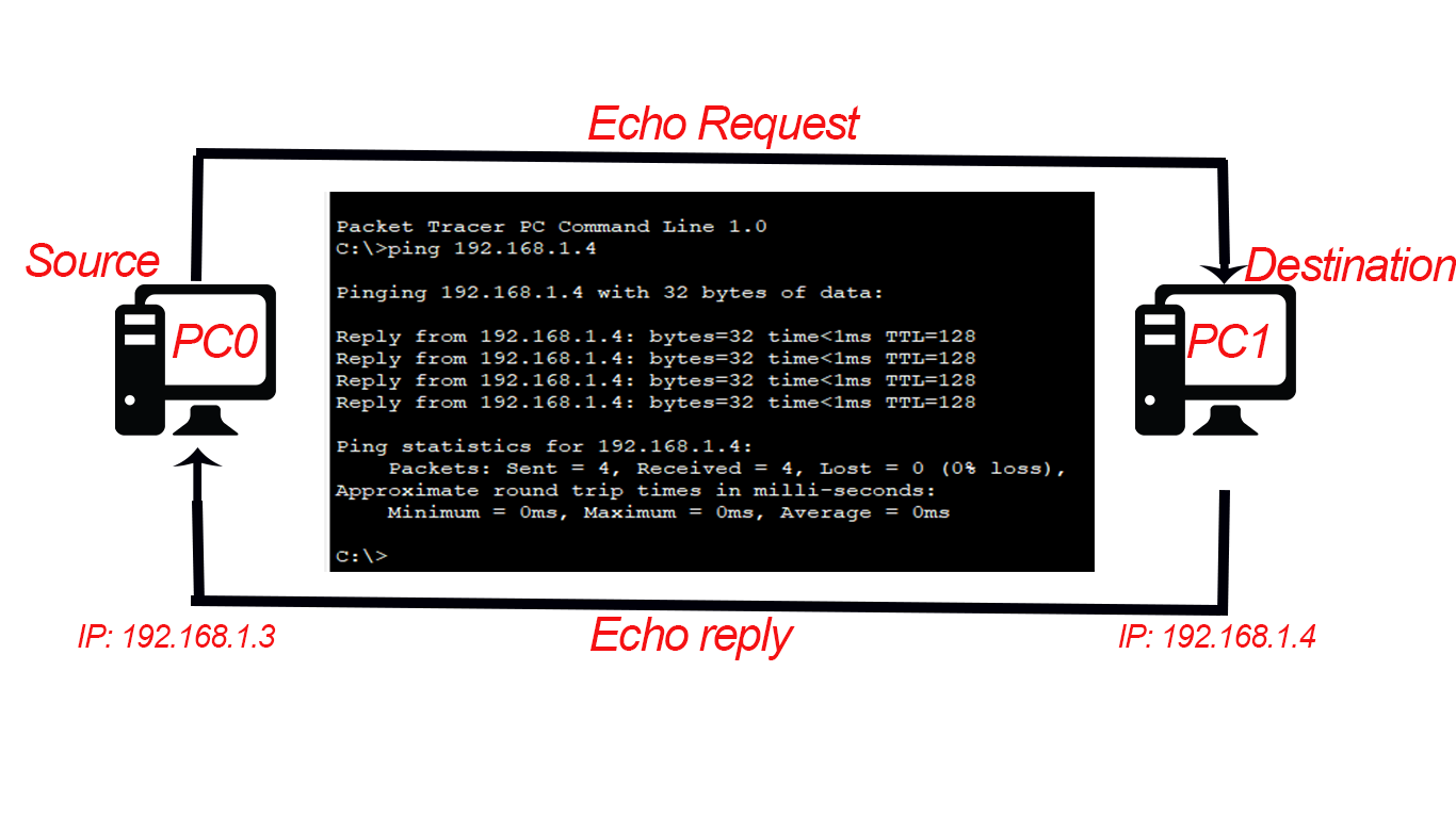
The time here is the period for going back and forth. Naturally, these values increase when we loosen up to a Public network. Variable time was like 1ms with Local networks. This event is called RTT(Round-trip Delay).
See the image below. PC0 sends a request to PC1 with ping. The first ICMP package from PC0 is called echo request. Then PC1 sends a signal, which is called echo reply. The time calculated for them to go from Source to Destination, then Destination to Source back is called RTT.
RTT
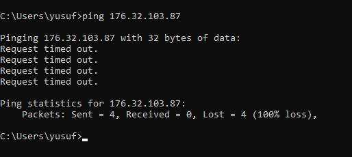
There are times that you don’t get a response:
ping-4
See, 4 packages were sent but there is no response, which means those packages are lost. Though, there is no information about the cause of this. To be informed about this, we use tracert instead of ping.
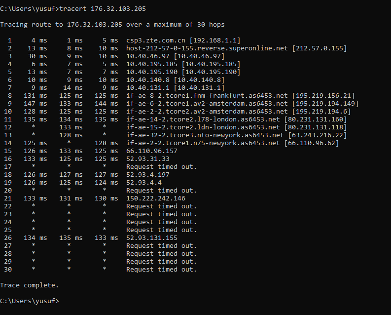
What is meant by “30 hops” is the number of bounces of signals going back and forth. 30 is the default value, which can you can change using parameters.
tracert
Displays the info of the time period for packages to go and return, whether if the router responded or not. Some rows have an asterisk for the time data, which means those packages either didn’t return or got lost.
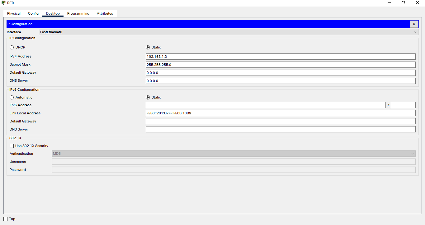
APIPA is basically used to assign private IPs just like DHCP. Remember back the Packet Tracer screen we have. There are 2 PCs but not a router. Let’s see who assigns the IP then.
APIPA-1
IIRC, we assigned IP addresses manually, but there is option DHCP too. Choose that.
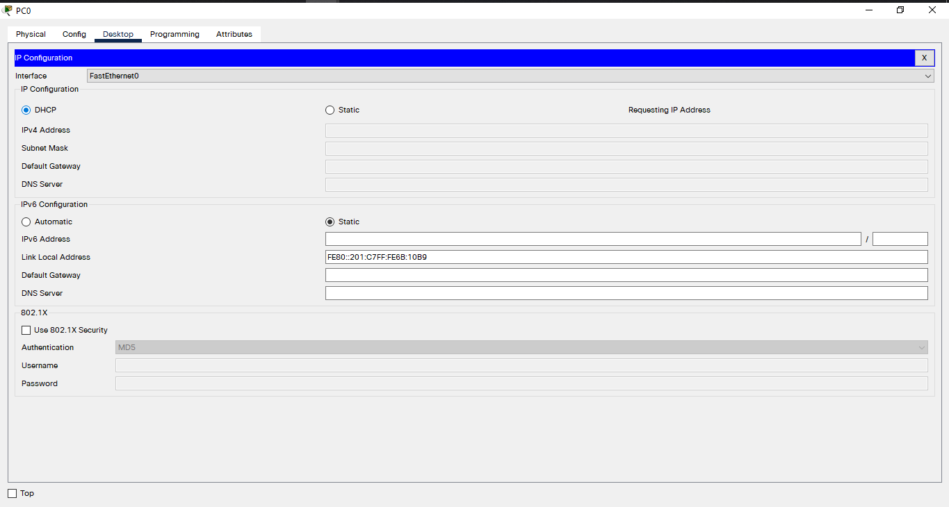
APIPA-2
Thus, a request for an IP address is sent but the “DHCP failed, APIPA is being used.“. Yet an IP address is assigned.
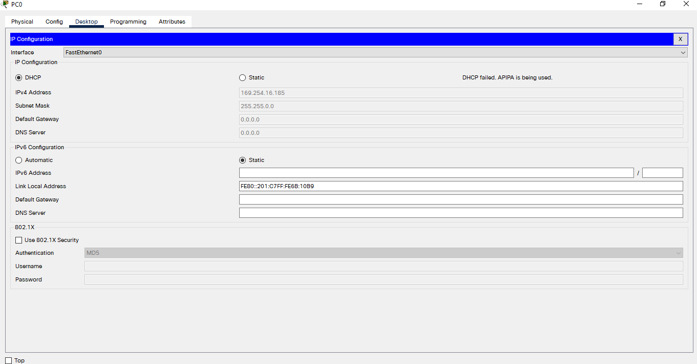
APIPA-3
What happens here is we requested an IP from DHCP but there were no DHCP servers. Then the Operating System got an IP from APIPA, assigning it, the IP address with “169.254”.
In brief, APIPA addresses start with 169.254 and they let us channel in only a network. Opening up publicly is not possible.
At Simulation Tab, we can lively display the packages in a network.
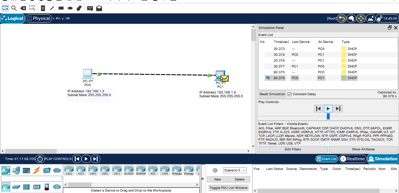
Simulation-tab
While the APIPA works because the DHCP has failed, DHCP re-request every 60 seconds to get rid of the APIPA, having another IP address.
As you can see from the image, PC0 requested something in 30th and 90th seconds.
Now let’s manually assign an IP address to PC0 and let PC1’s remain DHCP.
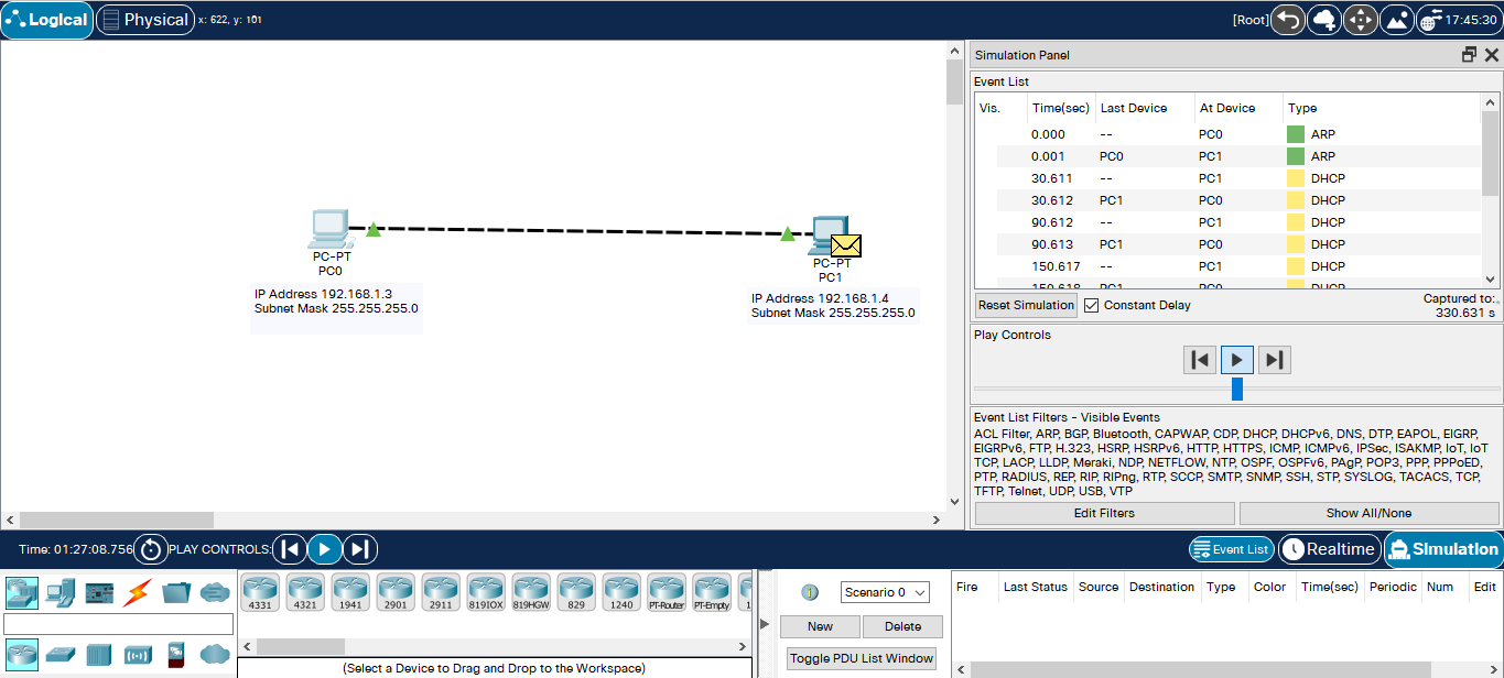
Simulation-tab-2
PC0 directly requested ARP but not the DHCP. With a bug in older versions, the device would request DHCP even though you assigned it manually. Now PC1 still requests DHCP even with the DHCP marked.
That’s it for the second part. Later.
https://www.udemy.com/course/cisco-ag-uzmanligi/
https://docs.microsoft.com/en-us/windows-server/administration/windows-commands/ping
https://www.mshowto.org/tracert-komutu-nedir-nasil-kullanilir.html
https://support.microsoft.com/tr-tr/topic/windows-da-tracert-yardımcı-programını-kullanarak-tcp-ip-sorunlarını-giderme-e643d72b-2f4f-cdd6-09a0-fd2989c7ca8e

 www.geeksforgeeks.org
[EN] CCNA Study Notes – 2
Hi. Last time we mentioned the basics and set up a PC-PC network. Now we will go into more detail about Packet Tracer.
Picking The Right Cable
Naturally, not every network devices connect with the same cable type as there are lots of them. Some connect with fiber cable, some with another. So, we should choose the right cable for a successful connection.
Cable types can be seen in Packet Tracer.

connections
We will move on referencing this cheat sheet of cable types:
Cross-over cable
- PC-PC = Cross-over cable
- Hub-Hub = Cross-over cable
- Switch-Switch = Cross-over cable
- Router-Router = Cross-over cable
- PC-Router = Cross-over cable
- Hub-Switch = Cross-over cable
Straight Cable
- PC-Hub = Cross-over cable
- PC-Switch = Cross-over cable
- Router-Switch = Cross-over cable
- Router-Hub = Cross-over cable

copper cross-over
Cross-over Cable
Drag two computers and choose Cross-Over cable. Then, right-click on PC0, click FastEthernet0.

Cross-over-1
Now we have another tip to connect another device. Click PC1, choose FastEthernet0 for that.

Cross-over-2
We have a successful connection. You can tell that from the green arrows appearing on the cable.

Cross-over-3
You can do this with other devices too. Let’s do another one on Hubs
Drag two Hubs from NetworkDevices and connect them with Cross-over.

Cross-over-4

Cross-over-5

Cross-over-6
PC and Hubs work fine plugging and unplugging if there are no logical mistakes.
But with Switches, it works differently. Because they don’t light green after plugging.
Choose GigabitEthernet0/1 on Switches with Cross-over cables.

Cross-over-7
As you can see, Switches don’t directly go green like others. It’ll go green in a minute.

Cross-over-8
Why this happens is because the interfaces in Switch do STP protocol and it takes about a minute to do that, then it’s green.

Cross-over-9
If it doesn’t go green in a minute, speed up the time from Play Control below.
With PC-PC, Hub-Hub, and Switch-Switch networks, a configuration isn’t needed, unlike Routers. Routers won’t connect without a configuration.

Cross-over-10

Cross-over-11
Straight-Through Cable
You need a straight-through cable for, say, PC-Hub. Choose FastEthernet0 with both having straight-through cable.

Straight-Through-1

Straight-Through-2

Straight-Through-3
Switch-Router and Router-Hub connections will always light red unless you configure the Router.

Straight-Through-4
Here as you can see, the same devices have Cross-over, and different devices have StraightThrough cables. Except for the PC-Router connection which has the Cross one.

Cross-over-13
IP Address Assigning
With the Packet Tracer’s feature, I mark the IP addresses for devices. You could use the N shortcut for that.

IP atama-1
To assign, click one of the devices. You should see something like this:

IP atama-2
Click Desktop, then IP Configuration.

IP atama-3
Assigning can be done in both ways: with DHCP or manually. To assign manually, type the IP address somewhere about IPv4 Address. It defined Subnet Mask itself.

IP atama-4
Do the same with the other device:

IP atama-5
Now the addresses are defined but we don’t know if there is anything incorrect. To test for it, use Command Prompt. To do so, click the device once more, then choose Command Prompt from Desktop.

IP atama-6
Do ipconfig to see the IP address:

Font Size – 3
IP addresses are correctly assigned as we defined.

IP atama-8
To channel in-network, Devices require MAC addresses too.
MAC Address Configuration.
MAC Adresses are structures made up of 48 bits.
Do ipconfig /all to view a MAC address.

MAC-Address-1
That’s all to know about MAC Addresses for now.
Ping
Now we will have to check if the devices can channel each other. For that, do ping [other device’s IP address]

ping-1
If you can ping a device, you are able to channel that device.
Ping uses a protocol named ICMP. ICMP is used to see network devices’ state. The image shows that 32-byte packets arrive below 1ms. Sending 4 packages, 4 packages arrived. 8 Packages are mutually being sent or received.

ping-2
You don’t just check on local devices with ping. You can also check with Public servers. Try this on your own device. Packet Traces can’t connect to our home networks.
Open CMD, do ping google.com

ping-3
The time here is the period for going back and forth. Naturally, these values increase when we loosen up to a Public network. Variable time was like 1ms with Local networks. This event is called RTT(Round-trip Delay).
RTT
See the image below. PC0 sends a request to PC1 with ping. The first ICMP package from PC0 is called echo request. Then PC1 sends a signal, which is called echo reply. The time calculated for them to go from Source to Destination, then Destination to Source back is called RTT.

RTT
There are times that you don’t get a response:

ping-4
See, 4 packages were sent but there is no response, which means those packages are lost. Though, there is no information about the cause of this. To be informed about this, we use tracert instead of ping.
Tracert
What is meant by “30 hops” is the number of bounces of signals going back and forth. 30 is the default value, which can you can change using parameters.

tracert
Displays the info of the time period for packages to go and return, whether if the router responded or not. Some rows have an asterisk for the time data, which means those packages either didn’t return or got lost.
APIPA
APIPA is basically used to assign private IPs just like DHCP. Remember back the Packet Tracer screen we have. There are 2 PCs but not a router. Let’s see who assigns the IP then.

APIPA-1
IIRC, we assigned IP addresses manually, but there is option DHCP too. Choose that.

APIPA-2
Thus, a request for an IP address is sent but the “DHCP failed, APIPA is being used.“. Yet an IP address is assigned.

APIPA-3
What happens here is we requested an IP from DHCP but there were no DHCP servers. Then the Operating System got an IP from APIPA, assigning it, the IP address with “169.254”.
In brief, APIPA addresses start with 169.254 and they let us channel in only a network. Opening up publicly is not possible.
Simulation Tab
At Simulation Tab, we can lively display the packages in a network.

Simulation-tab
While the APIPA works because the DHCP has failed, DHCP re-request every 60 seconds to get rid of the APIPA, having another IP address.
As you can see from the image, PC0 requested something in 30th and 90th seconds.
Now let’s manually assign an IP address to PC0 and let PC1’s remain DHCP.

Simulation-tab-2
PC0 directly requested ARP but not the DHCP. With a bug in older versions, the device would request DHCP even though you assigned it manually. Now PC1 still requests DHCP even with the DHCP marked.
That’s it for the second part. Later.
References
https://www.udemy.com/course/cisco-ag-uzmanligi/
https://docs.microsoft.com/en-us/windows-server/administration/windows-commands/ping
https://www.mshowto.org/tracert-komutu-nedir-nasil-kullanilir.html
https://support.microsoft.com/tr-tr/topic/windows-da-tracert-yardımcı-programını-kullanarak-tcp-ip-sorunlarını-giderme-e643d72b-2f4f-cdd6-09a0-fd2989c7ca8e

What is APIPA (Automatic Private IP Addressing)? - GeeksforGeeks
A Computer Science portal for geeks. It contains well written, well thought and well explained computer science and programming articles, quizzes and practice/competitive programming/company interview Questions.
 www.geeksforgeeks.org
Moderatör tarafında düzenlendi:
